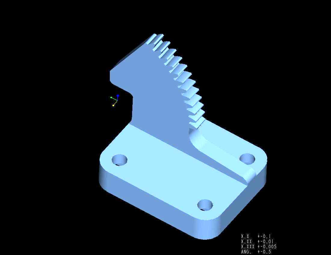
This part is attached to the lid of a printer and mates up with a dashpot to keep the lid from slamming shut. The part is modeled as a single piece but I decided to make it in 2 pieces to eliminate all of the hogging and make it easier to attach to my rotary table. The machine I used to make the gear teeth is an old Light machines TMC 1000 that I retrofitted with Ahha Artisan software and electronics that I assembled myself. More info on this machine can be found at:
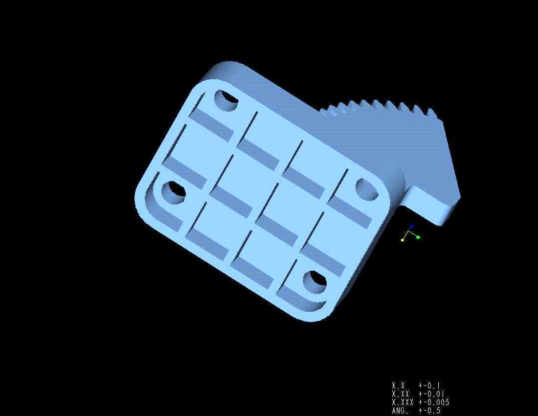
http://www.grifftek.com/light.htmThese are jpgs of the solid model as created in ProE
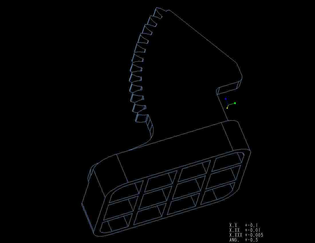
This is a wire frame jpeg image created in ProE
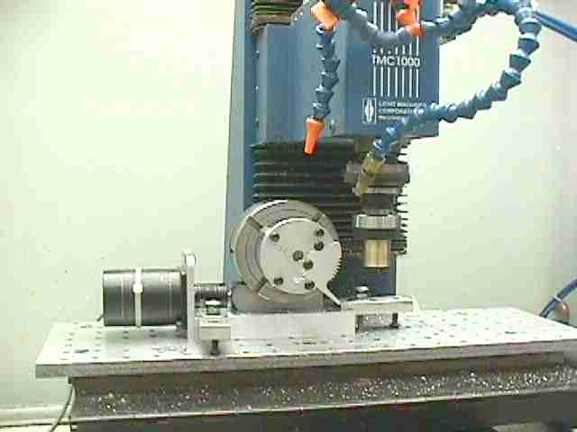
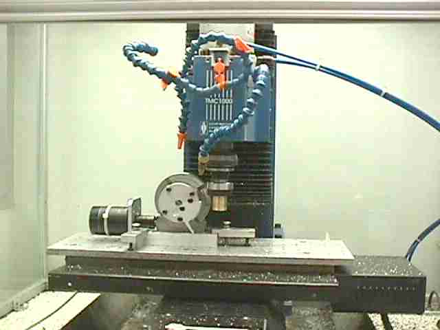
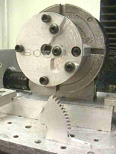
Here you can see an overall view of the setup used to make the gear portion.
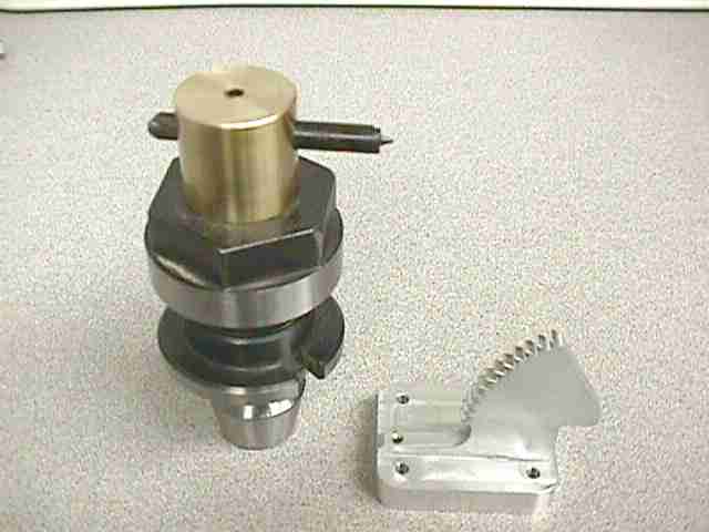
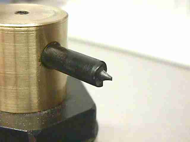
Here is the cutter that I fabricated using the tooth profile from the ProE model. I machined the profile into the end of a 1/4" drill that I annealed before machining on my CNC retrofitted EMCO Compact 8 lathe. You can find some images of the lathe at: http://www.grifftek.com/compact8.htm After the lathe work, I machined some relief into the top of the tool, sharpened the end of the homemade cutter on a diamond wheel before oil hardening the cutter. I also made the cutter holder, which is held in the Royal quick-change collet holder.

Here are a couple of shots of the cutter in action.
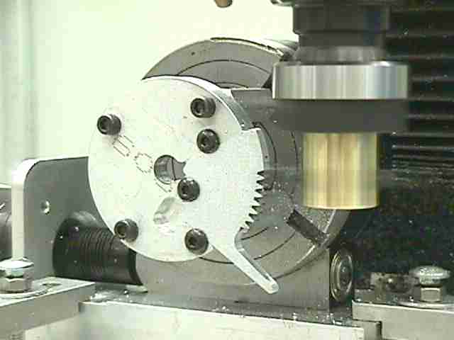
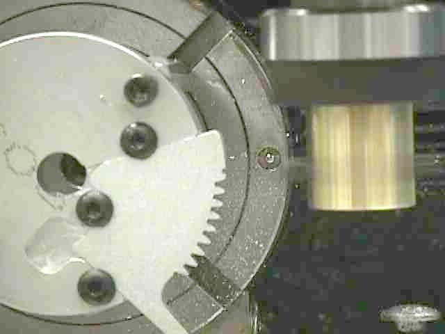
This is a shot of the fixture, which I fabricated to hold the gear blank while machining the teeth. The fixture is attached to the CNC retrofitted Sherline rotary table (http://www.grifftek.com/4th_axis.htm) with some standoffs to provide the necessary clearance for the cutter.
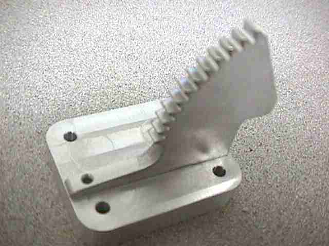
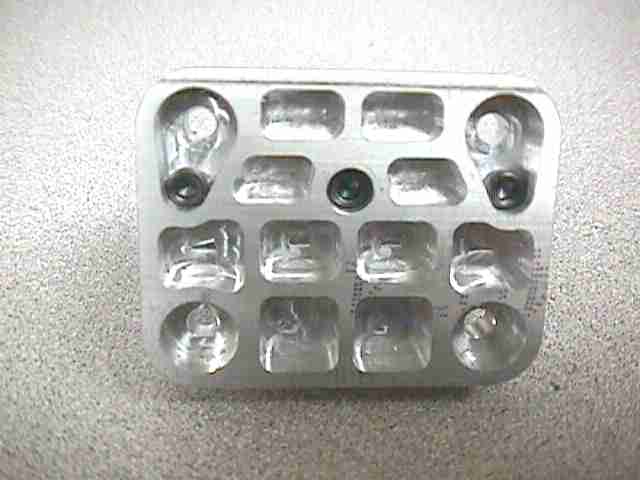
Here are some images of the finished gear assembled onto the base. The gear blanks, base and fixture were machined on the YCI SuperMax mill with Centroid control. (
http://www.grifftek.com/images/misc_images_no_html/magtek_shop_pics/Ycimill1.jpg)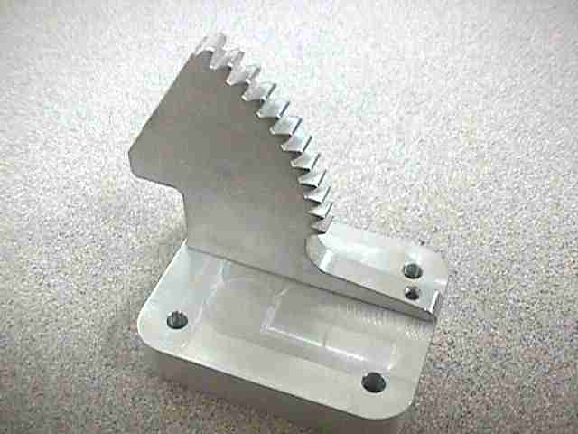
This is the code that I created for Ahha Artisan to cut the gear teeth, I have annotated it to make it easier to understand:
M03 ;Turn on the Spindle
%Counter=0 ;Sets counter to zero
%Counter2=0 ;Sets counter2 to zero
G01 X0.0 F100.0 ;Moves to start position in X
%Start1: ;Label for marking the start of the cutting motion macro.
G90 ;the next five lines are the toolpath which is repeated 20 times removing 0.0050" in X each pass.
G01 Y-.5 F20.0
G01 Y0.0 F50.0
G91
G01 X-0.005
%Counter=%Counter+1 ;Increments the counter by 1
If(%Counter GE 20) goto %Index ;when the tooth is cut, jump to the index portion of the program.
goto %Start1 ; jump to start label to repeat motion if the above statement is not satisfied
%Index: ;this is the label marking the beginning of the indexing macro.
G91
G00 X.5 ;Moves in X to provide clearance for indexing
G01 W4.8 F200. ;This indexes the rotary table 4.8 degrees
G01 X-.4 F35. ; Moves back to the starting position in X
%Counter=0 ;Resets the cutting motion counter to zero for the start of the next tooth.
G90
%Counter2=%Counter2+1 ;increments the counter tracking the number of teeth to be cut
If(%Counter2 GE 13) goto %End ;Checks to see if all 13 teeth are cut, if they are go to the label End
goto %Start1 ;returns to the cutting macro to cut next tooth.
%End: ;End of operation macro.
M05 ;Shuts off the spindle
G00 X1.5 ;Moves to clearance in X for indexing and changing part.
W-10. ;Moves past starting position for compensating table backlash.
W0. ;Moves to starting position on rotary axis.
Follow these links to other machining projects:
http://www.grifftek.com/images/misc/machined_parts/fuse_block/fuse_holder.htm
http://www.grifftek.com/images/misc/machined_parts/lathe_part_pcb_holder/pcb_holder.htm
http://www.grifftek.com/images/misc/machined_parts/sensormatic_demo/sensormatic_demo.htm
http://www.grifftek.com/images/misc/machined_parts/spindle/spindle.htm
http://www.grifftek.com/images/misc/machined_parts/spring_retainer/sprinr_retainer.htm
http://www.grifftek.com/images/misc/sample_parts/smp.html
Bill Griffin