|
|
|
Injection molded parts designed for ultrasonic
welding. We needed to assemble some beta test units for evaluation before
the tooling was completed for the Branson ultra sonic welder.
|
|
Injection molded parts designed for ultrasonic
welding. We needed to assemble some beta test units for evaluation before
the tooling was completed for the Branson ultra sonic welder.
|
|
Injection molded parts designed for ultrasonic
welding. We needed to assemble some beta test units for evaluation before
the tooling was completed for the Branson ultra sonic welder.
|
|
|
|
2 units were modified
by hand with an xacto knife. This was too time consuming and not feasible
for making 150 units.
|
|
|
|
|
|
|
|
|
|
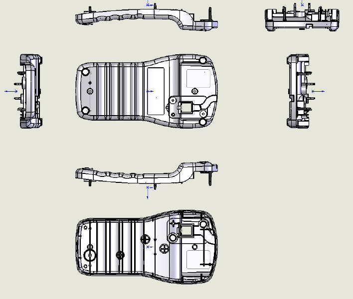
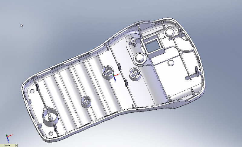
From this slide you can
see that there are virtually no flat surfaces to hold the part for
modification
|
|
|
|
|
|
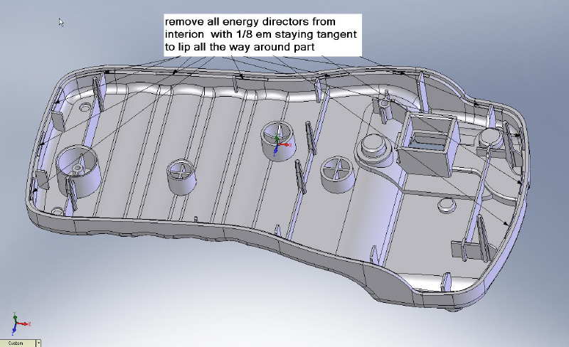
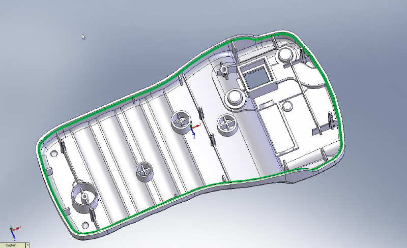
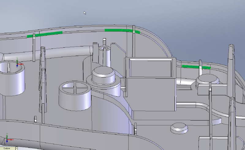
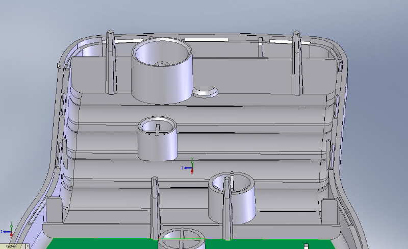
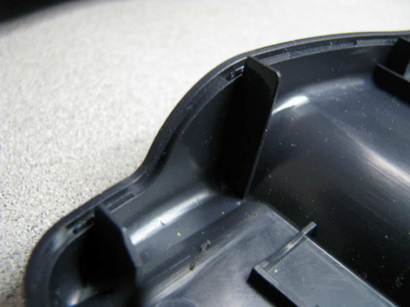
Here you can see the surface with the energy directors
removed.
|
|
|
|
|
|
|
|
|
|
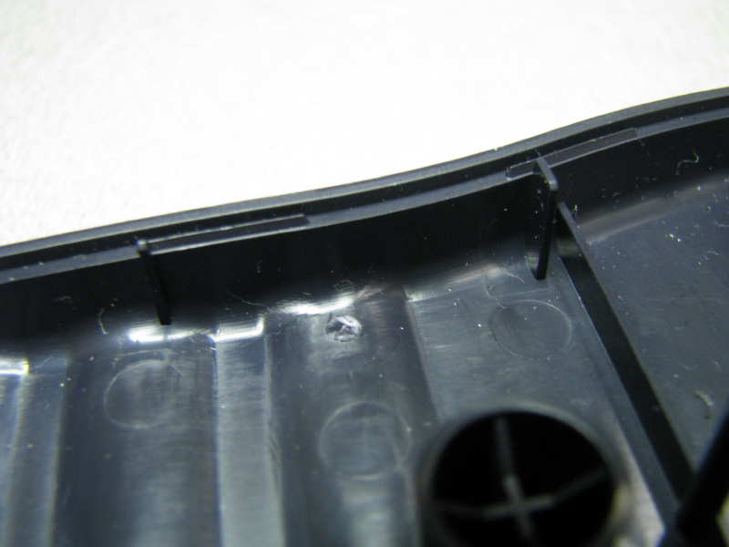
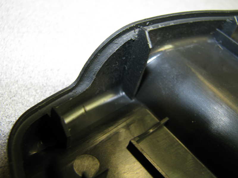
This is a photo of the
actual part with the energy directors visible
|
|
|
|
|
|
|
Model of the housing
with energy directors
|
|

|
|
|
|
|
|
|
|
|
|
|
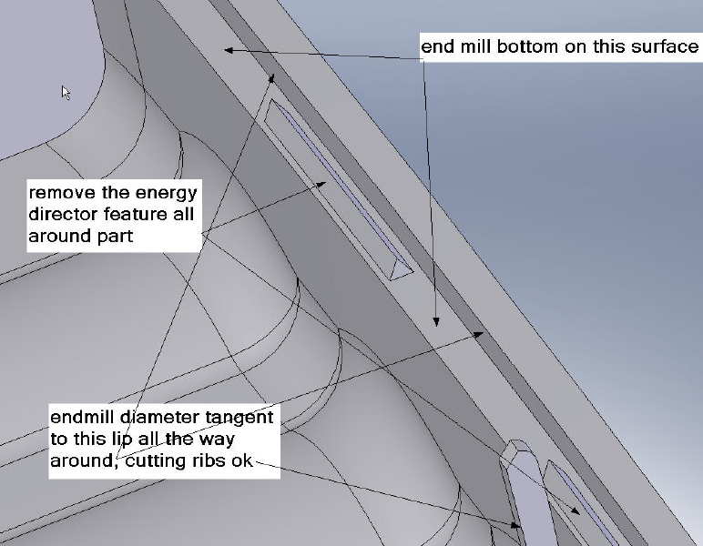
From this view you can see the elevation changes the tool
must follow to cut off the energy directors.
|
|
|
|
|
|
|
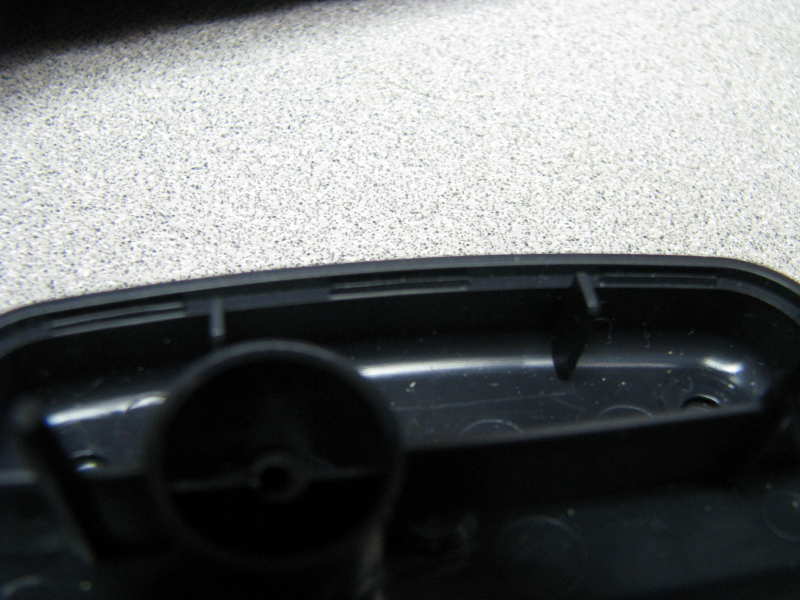
Another
photo of the actual part
|
|
|
|
|
|
|
|
|
|
|
Its curved along this
part of the path as well
|
|
|
|
|
|
|
|
|
|
|
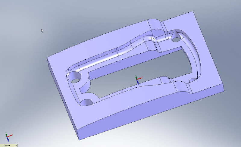
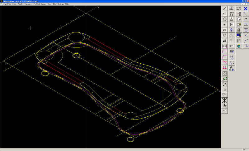
This is the solid model
of the fixture design from solidworks.
|
|
|
|
|
|
|
|
|
|
|
|
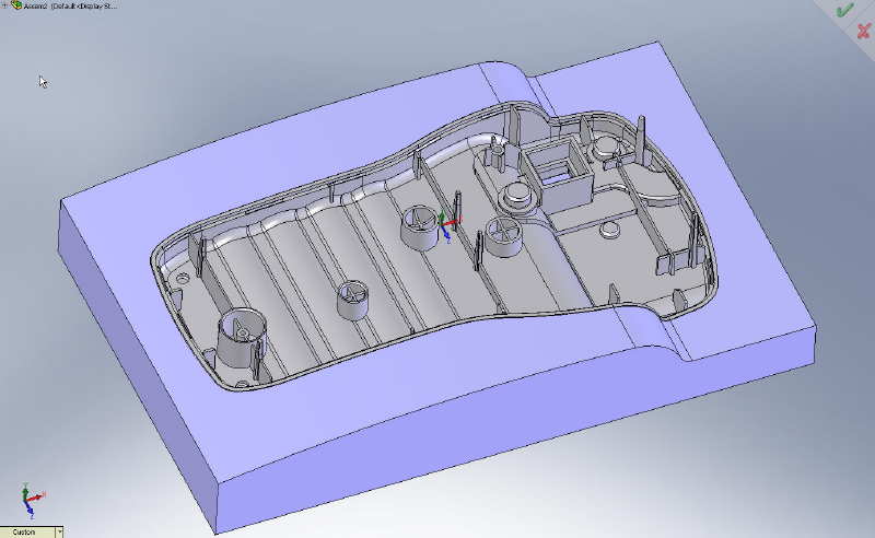
Solid model with the
part model inserted in the fixture.
|
|
|
|
|
|
|
|
|
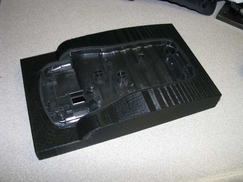
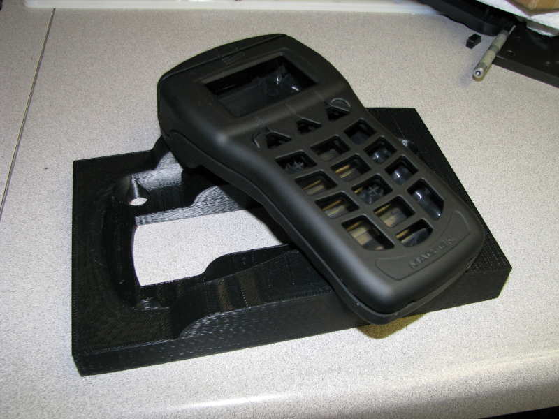
We used out Stratasys FDM machine to build the fixture
in PCABS blend material. The fixture was built using the sparse feature
of the insight software so the inside of the part is corrugated. I made the
“skin” of the fixture 0.080” thick. Build time was less than 5 hours
built sparse vs. a full solid build which would have taken just over 10
hours.
The part is clamped from the sides when the fixture is
squeezed by the vise. This changes the position of the part slightly
which must be corrected but it holds the part sequrely and is easy to
load and unload without any clamps to avoid.
The part has a rubber like coating on the outside and
this also helps keep it secure in the fixture when squeezed.
|
|
|
|
|
|
|
|
|
|
|
Here you can see the assembled housing. Note that the part
doesn’t fit together correctly because of the energy directors
|
|
|
|
|
|
|
|
|
|
|
Here you can see both a flat 2d geometry layer at Z0
as well as the 3d tool path layer. The actual path geometry was offset
from the model in mastercam by my friend Terence which was then imported
into GP to post.
|
|
|
|
|
|
|
|
|
|
|
A picture of the cut
part
|
|
|
|
|
|
|
A picture of the un-cut part
|
|
|
|
|
|
|
|
|
|
|
|
|
|
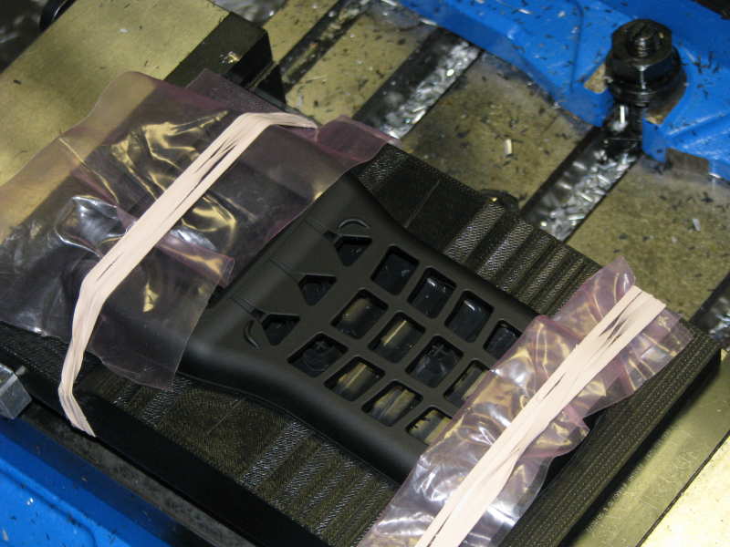
We were able to recycle
the fixture to hold the top cover to increase the clearance around the
1-9 keys
Rubber bands were the
easiest way to hold the housing in the fixture for machining…..Don’t
laugh, it worked and I didn’t have to add any clamps to the fixture
(remember that it is essentially hollow inside because it was built
sparse by the FDM machine)
|
|
|
|
|
|


