|
|
|
gb_head_assembly_video1
|
|


|
|
Click on the small camera icon above for a short video showing the
machine in motion
|
|
|
|
|
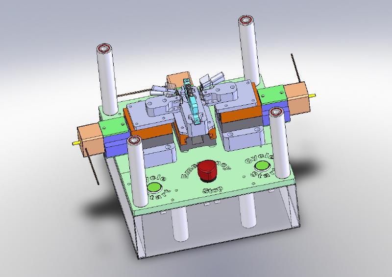
Gilbarco Assembly
Machine-1 ASM
|
|
|
|
|
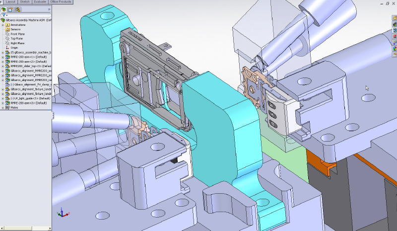
This machine is used to insert
magnetic heads into a reader body in the correct location while being
able to control very precisely the gap between the “Crowns” of the 2
heads. The reason for controlling this gap is to lower the head to stripe
contact force to reduce the feel of the drag on the card as it is
inserted and removed the reader.
|
|
This
assembly fixture is one of the best examples of a project that pretty much
encompasses all of my skill sets in one project.
The
Concept, Engineering, CAD, CAM, and
execution is all my work, no one else
was involved in bringing this fixture to life.
|
|
|
|
|
|
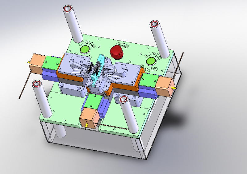
Gilbarco
Assembly Machine-2 ASM
|
|
|
|
3/8/2011 9:26:24 AM
|
|
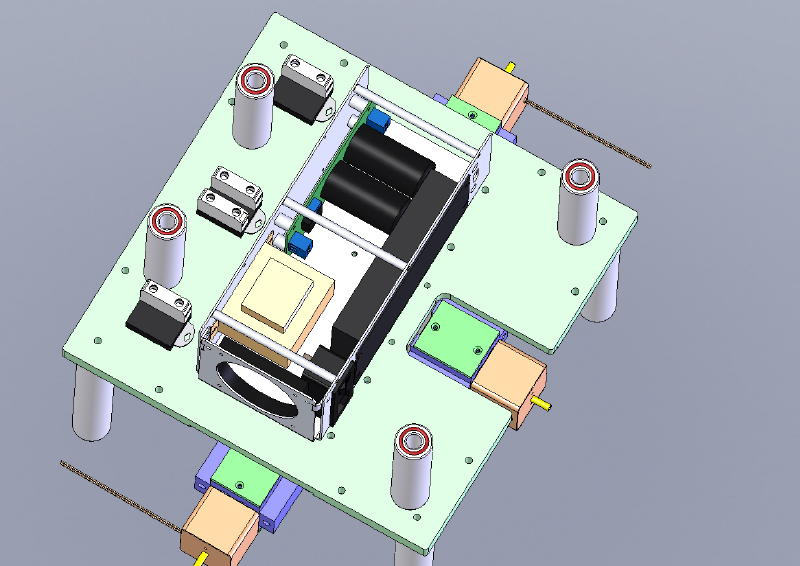
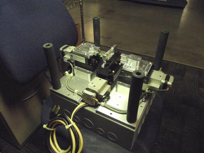
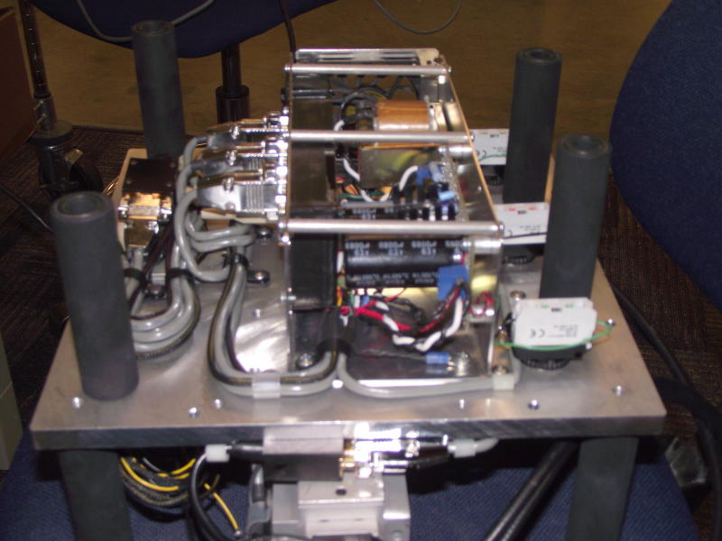
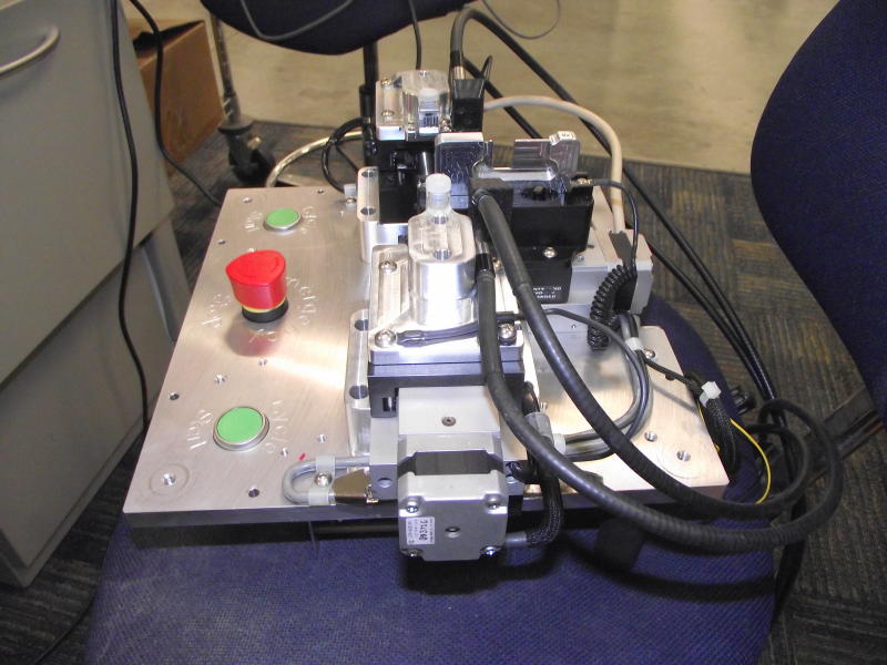
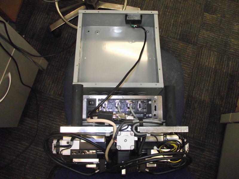
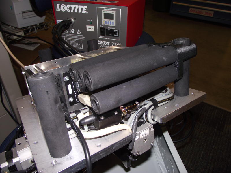
The legs shown attached to the top surface are normally
stored inside of the case and are used when the machine is being service
and access to the components on the bottom side of the fixture is necessary.
|
|
|
Gilbarco Assembly
Machine-3 ASM
|
|
|
|
|
3/8/2011 9:26:24 AM
|
|
In this shot of the 3d model, you can see there are 4
legs on the underside of the fixture as well so that when it has been
removed from the enclosure it has legs to stand on. There are more shots of
the leg implementation at the bottom of the page.
|
|
|
|
|
|
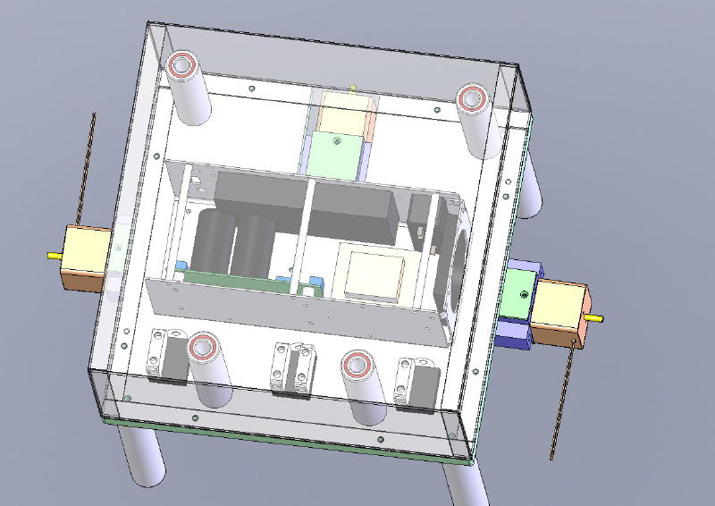
Gilbarco
Assembly Machine-4 ASM
|
|
|
|
3/8/2011 9:26:24 AM
|
|
|
|
|
image003
|
|
|
|
|
3/8/2011 9:26:24 AM
|
|
The heads are secured to the reader body using UV cured
adhesive applied to the heads prior to the machine placing them in
alignment. The software running the machines controls the UV light source
turning it on at the appropriate time and duration to cure the adhesive.
|
|
|
|
|
|
DSCF2138
|
|
|
|
FinePix
S1800
2/16/2011 6:43:29 PM
|
|
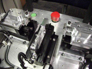
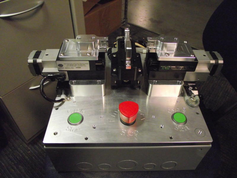
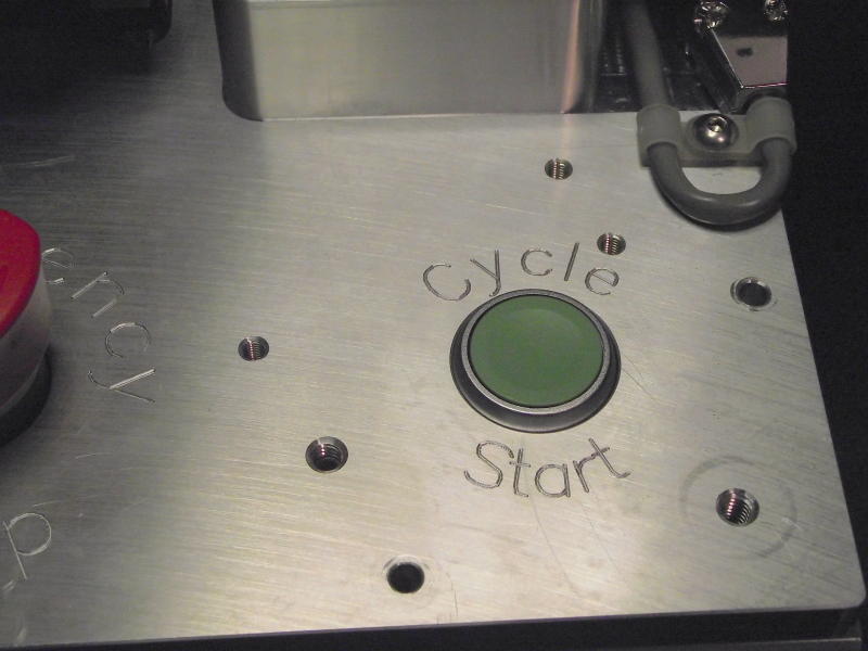
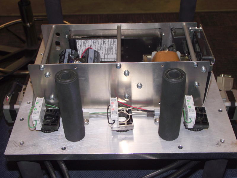
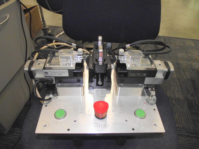
The machine is controlled using
the Mach 3 CNC control software and a Gecko G540 4 axis stepper motor
controller to drive the linear stages. I created custom macros and did all
of the G-code programming needed to control the machine.
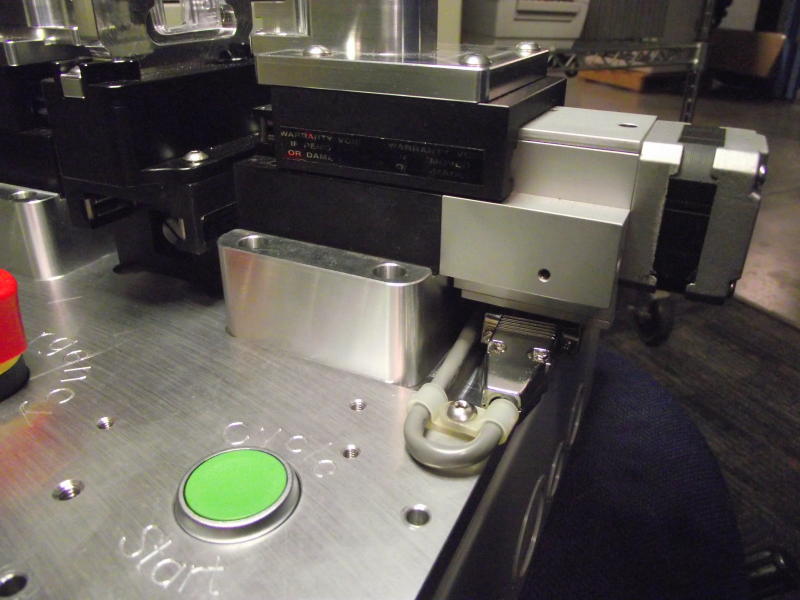
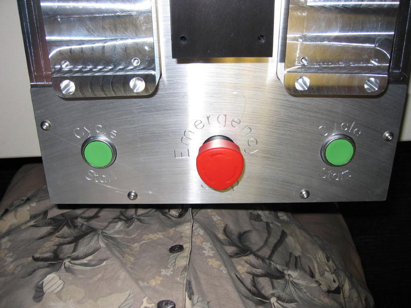
Machine operation is started by
depressing both green buttons simultaneously to start the alignment
sequence.
Once the heads have had adhesive
applied to them, they are placed in the head holders on the opposing head
slides. The center slide moves to the measurement position then each head
slide approaches the measurement plate. Once it completes the probing
routine both heads are moved to the retract position so the center slide
with the reader body attached can move to the assembly position. Once in
the correct position, both heads are simultaneously moved into mounting
position with the desired head gap between the crowns. The UV light sourced
is energized for the proper amount of time to cure the adhesive. After
curing, the heads are released from the head holders as they are now
adhered to the reader body. Cycle start is once again initiated by pressing
both green buttons and the head slides retract to the loading position and
the center slide moves back to the load/ measure location. All of this is
controlled by the parameters in the software which are easily changed if
desired.
|
|
|
DSCF2140
|
|
|
|
|
FinePix S1800
2/16/2011 6:43:57 PM
|
|
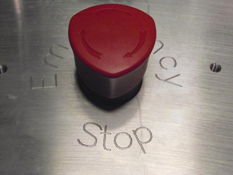
Emergency Stop switch should a cycle need to be stopped
mid sequence!
|
|
|
|
|
|
DSCF2141
|
|
|
|
FinePix
S1800
2/16/2011 6:44:06 PM
|
|
|
|
|
DSCF2143
|
|
|
|
|
FinePix S1800
2/16/2011 6:44:19 PM
|
|
Head Holder #1
|
|
|
|
|
|
DSCF2145
|
|
|
|
FinePix
S1800
2/16/2011 6:44:33 PM
|
|
Head Holder #2
|
|
|
DSCF2146
|
|
|
|
|
FinePix S1800
2/16/2011 6:44:46 PM
|
|
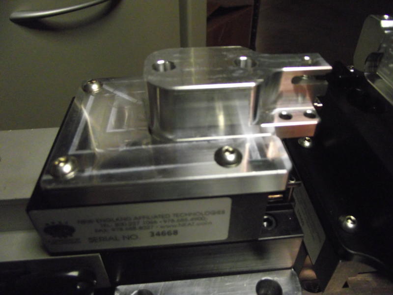
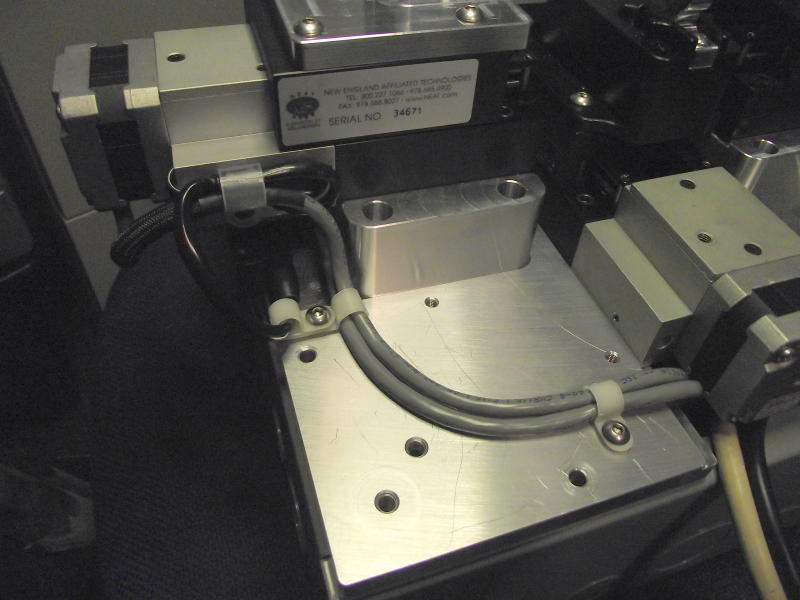
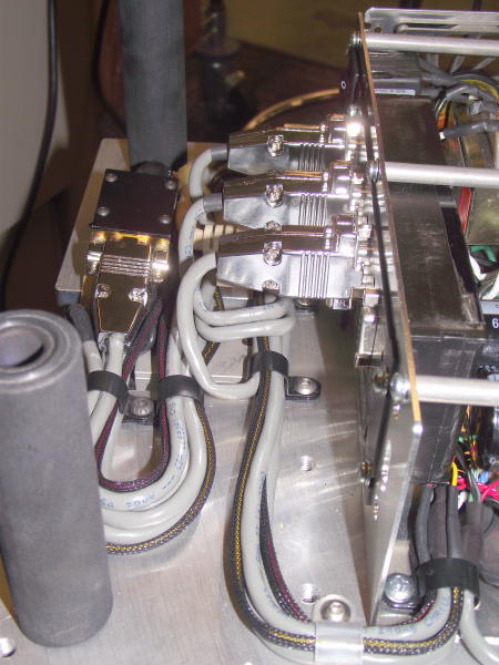
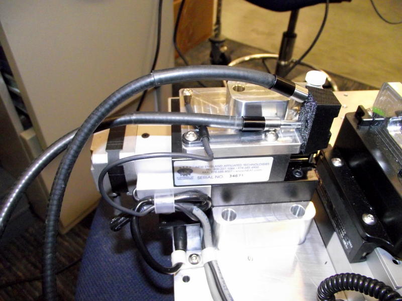
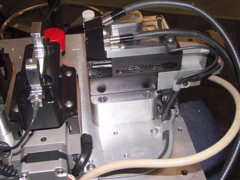
Notice the cable management and the nicely machined
parts. I take the time to program and machine chamfer all of the edges of
my machined parts whenever possible, it makes for some very clean and
professional looking parts.
|
|
|
|
|
|
DSCF2147
|
|
|
|
FinePix
S1800
2/16/2011 6:44:52 PM
|
|
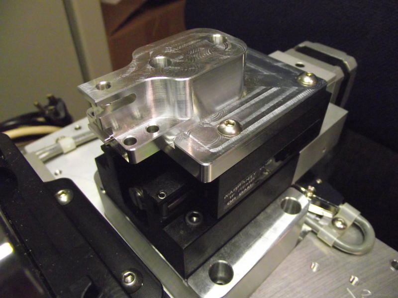
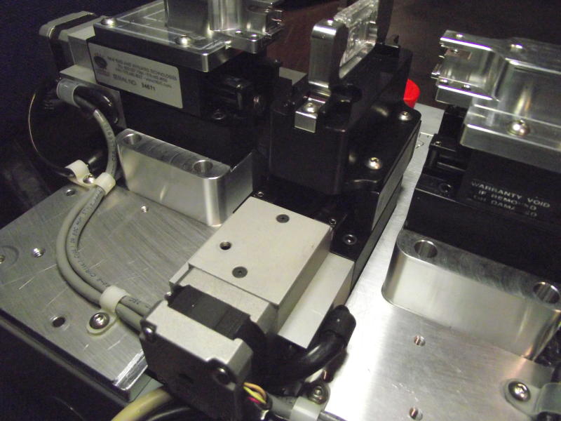
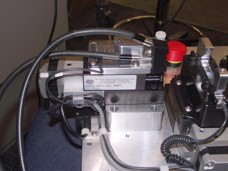
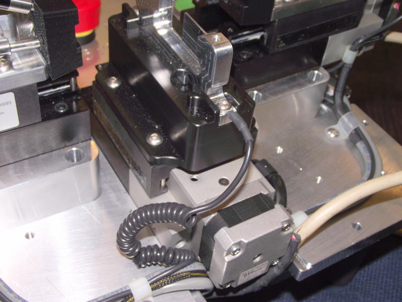
More cable management!
|
|
|
DSCF2148
|
|
|
|
|
FinePix S1800
2/16/2011 6:44:59 PM
|
|
|
|
|
|
|
|
DSCF2149
|
|
|
|
FinePix
S1800
2/16/2011 6:45:06 PM
|
|
|
|
|
DSCF2150
|
|
|
|
|
FinePix S1800
2/16/2011 6:45:48 PM
|
|
|
|
|
|
|
|
DSCF2153
|
|
|
|
FinePix
S1800
2/16/2011 6:47:11 PM
|
|
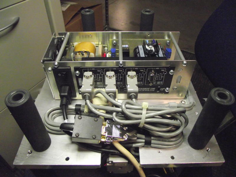
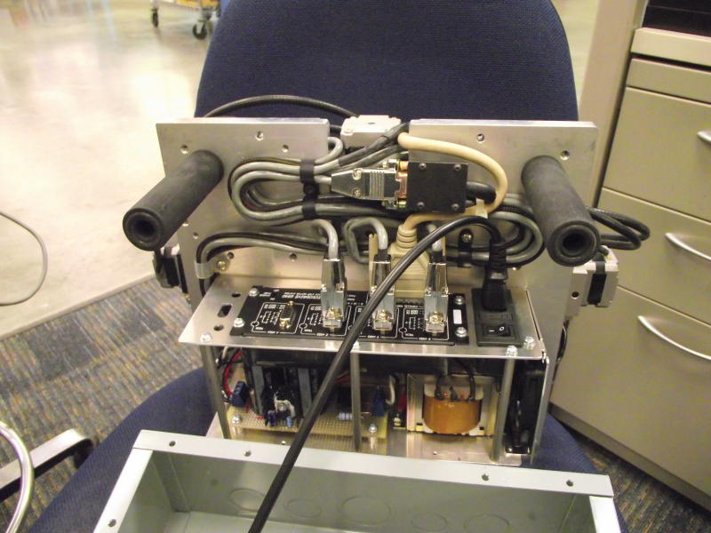
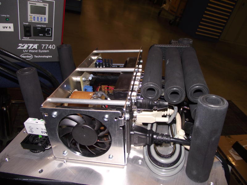
Here you can see the 4
axis G504 Gecko stepper motor controller. I designed the sheet metal part in
Solidworks using the sheet metal module. I then flattened it in Solidworks
and then CNC machined the flat pattern. Once complete, I folded the sheet
metal using the box and pan break. I machined up all of the spacers, hand
built the power supply board, installed the power transformer, fan, and
power inlet module.
|
|
|
DSCF2155
|
|
|
|
|
FinePix S1800
2/16/2011 6:47:56 PM
|
|
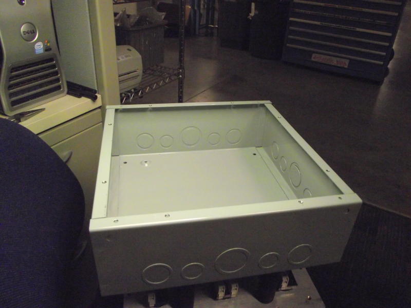
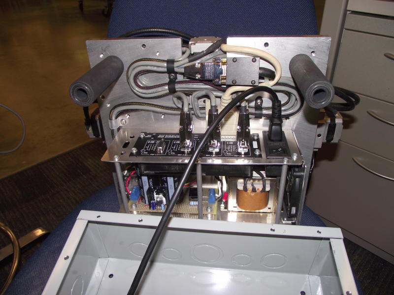
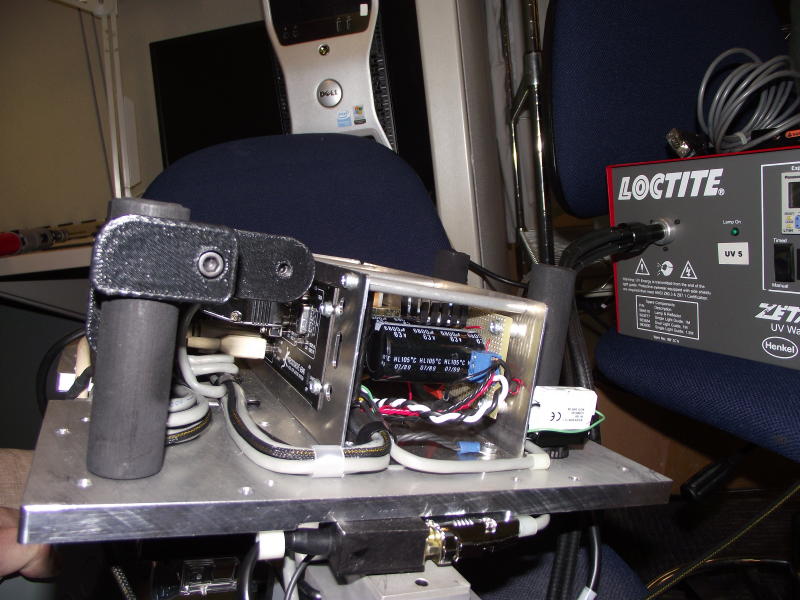
I like to use these NEMA
electrical boxes for enclosures and I try to just use them as a cover. I
prefer to be able to completely remove my fixture from the box without
components mounted to the box and to the fixture with cables in-between, I
have found that this makes for a very clean and easily serviceable setup.
And most importantly it prevents wires from being damaged in the service
process.
|
|
|
|
|
|
DSCF2214
|
|
|
|
FinePix
S1800
3/3/2011 12:47:21 PM
|
|
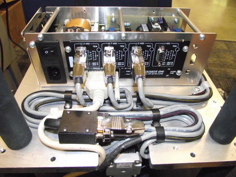
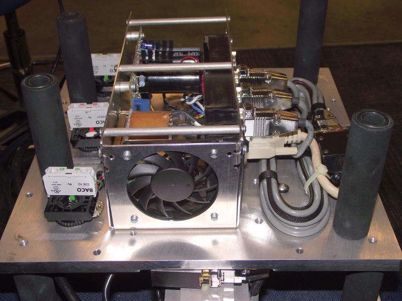
A nice shot of the controller / power supply module and
the nicely managed cables!
|
|
|
DSCF2217
|
|
|
|
|
FinePix S1800
3/3/2011 12:47:55 PM
|
|
|
|
|
|
|
|
DSCF2218
|
|
|
|
FinePix
S1800
3/3/2011 12:48:04 PM
|
|
|
|
|
DSCF2219
|
|
|
|
|
FinePix S1800
3/3/2011 12:49:27 PM
|
|
|
|
|
|
|
|
DSCF2220
|
|
|
|
FinePix
S1800
3/3/2011 12:49:39 PM
|
|
|
|
|
DSCF2221
|
|
|
|
|
FinePix S1800
3/3/2011 12:49:49 PM
|
|
|
|
|
|
|
|
DSCF2223
|
|
|
|
FinePix
S1800
3/3/2011 12:51:41 PM
|
|
|
|
|
DSCF2224
|
|
|
|
|
FinePix S1800
3/3/2011 12:51:57 PM
|
|
|
|
|
|
|
|
DSCF2225
|
|
|
|
FinePix
S1800
3/3/2011 12:52:19 PM
|
|
|
|
|
DSCF2226
|
|
|
|
|
FinePix S1800
3/3/2011 12:52:28 PM
|
|
|
|
|
|
|
|
DSCF2227
|
|
|
|
FinePix
S1800
3/3/2011 12:52:42 PM
|
|
|
|
|
DSCF2228
|
|
|
|
|
FinePix S1800
3/3/2011 12:52:50 PM
|
|
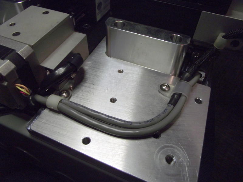
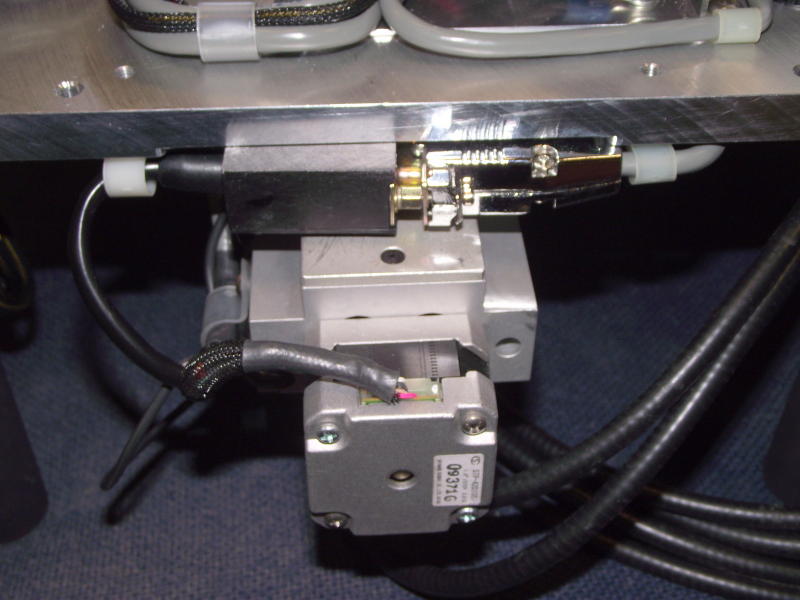
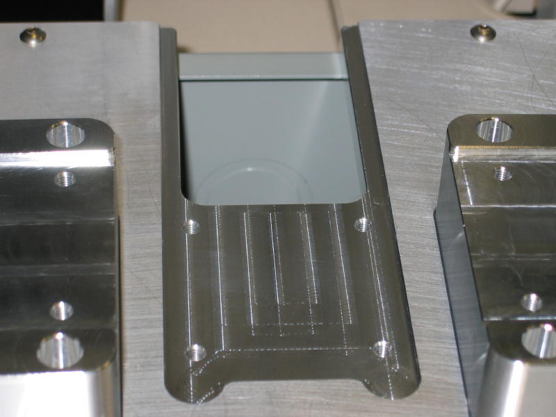
In this photo you can see the measurement plate mounted
to its Delrin isolation block and the coiled cord used for the continuity
probing circuit. While not present, you can see the pocket and blade that
holds the reader body on the measurement plate.
|
|
|
|
|
|
DSCF2229
|
|
|
|
FinePix
S1800
3/3/2011 3:00:48 PM
|
|
|
|
|
DSCF2230
|
|
|
|
|
FinePix S1800
3/3/2011 3:00:55 PM
|
|
|
|
|
|
|
|
DSCF2231
|
|
|
|
FinePix
S1800
3/3/2011 3:01:16 PM
|
|
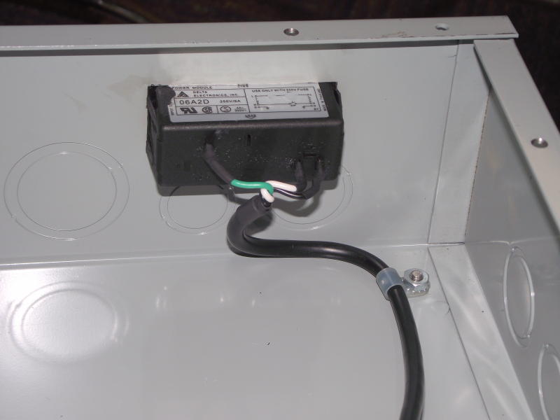
Here you can see the power cable
that is attached to the power inlet mounted to the enclosure itself but it is
easily removed from the power inlet on the Controller chassis for service
if necessary.
|
|
|
DSCF2232
|
|
|
|
|
FinePix S1800
3/3/2011 3:01:25 PM
|
|
Enclosure mounted power inlet
with power cable strain relief.
|
|
|
|
|
|
DSCF2234
|
|
|
|
FinePix
S1800
3/4/2011 10:29:48 AM
|
|
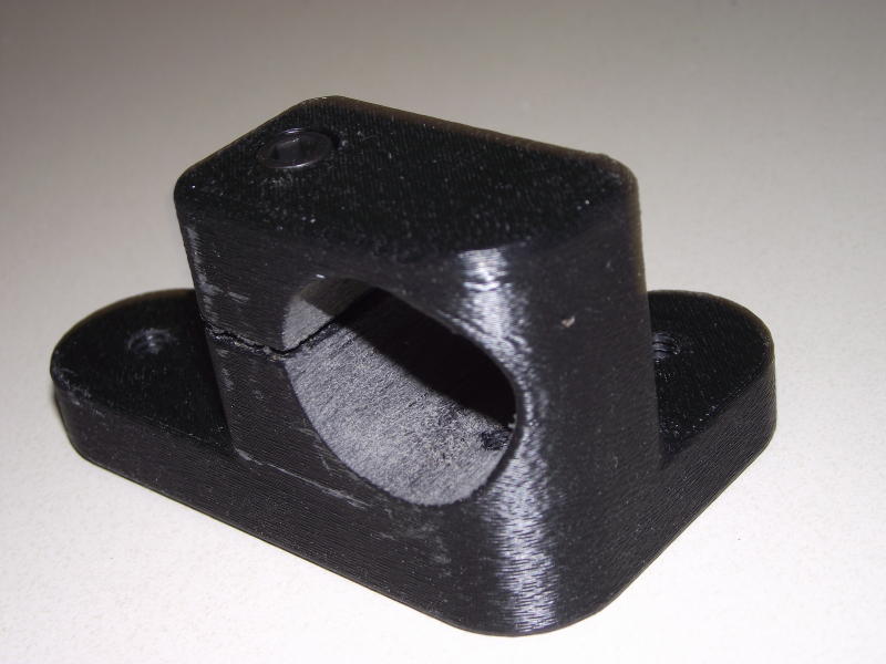
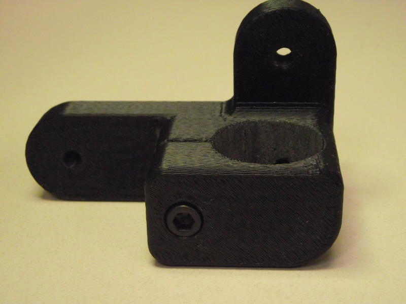
This is the bracket that
attaches to one of the internal legs on the bottom side of the fixture. It
is used to hold the 4 legs from the top of the fixture plate when the unit
is not being serviced. This keeps them handy for service but neatly secured
inside the enclosure.
|
|
|
DSCF2235
|
|
|
|
|
FinePix S1800
3/4/2011 10:29:55 AM
|
|
|
|
|
|
|
|
DSCF2236
|
|
|
|
FinePix
S1800
3/4/2011 10:30:05 AM
|
|
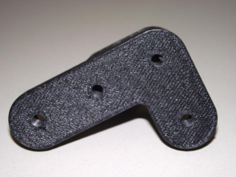
Another shot of the leg
storage clamp. Notice the socket head cap screw used to clamp the holder to
the internal leg.
|
|
|
DSCF2237
|
|
|
|
|
FinePix S1800
3/4/2011 10:30:52 AM
|
|
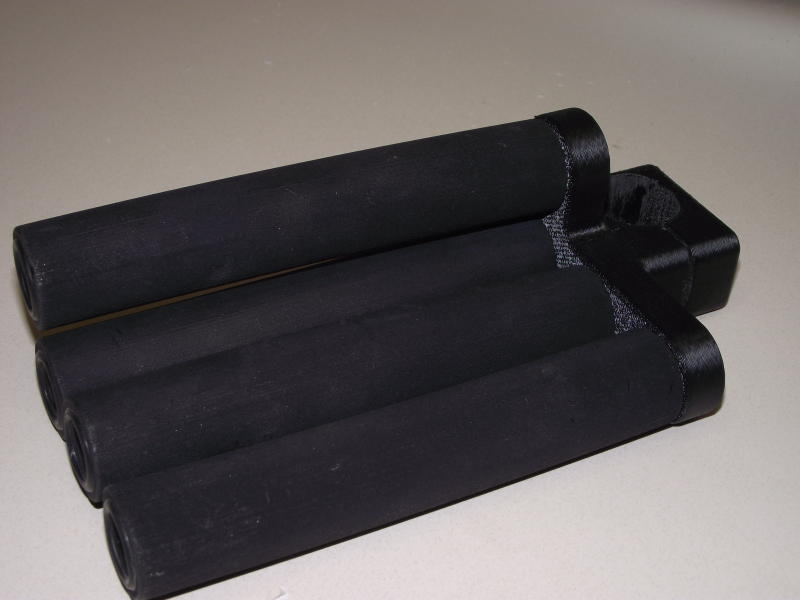
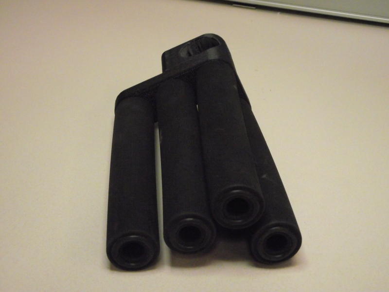
4 legs screwed into the
mounting bracket
|
|
|
|
|
|
DSCF2238
|
|
|
|
FinePix
S1800
3/4/2011 10:30:57 AM
|
|
Here you can see the legs
attached to the storage clamp. Of interest here is the O-rings used as
rubber feet that are attached to the legs. The groove they reside in has an
undercut circular groove which is easily created using the 3d printer.
|
|
|
DSCF2239
|
|
|
|
|
FinePix S1800
3/4/2011 10:31:04 AM
|
|
|
|
|
|
|
|
DSCF2240
|
|
|
|
FinePix
S1800
3/4/2011 10:32:19 AM
|
|
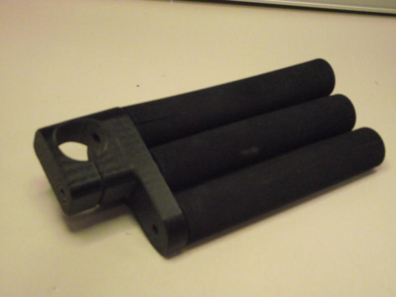
And finally, you can see the
legs in the storage position mounted to one of the internal legs.
|
|
|
DSCF2241
|
|
|
|
|
FinePix S1800
3/4/2011 10:32:32 AM
|
|
|
|
|
|
|
|
DSCF2242
|
|
|
|
FinePix
S1800
3/4/2011 10:33:21 AM
|
|
|
|
|
image014
|
|
|
|
|
Canon PowerShot S400
5/11/2010 9:26:19 AM
|
|
|
|
|
|
|
|
image015
|
|
|
|
Canon
PowerShot S400
5/11/2010 9:26:49 AM
|
|
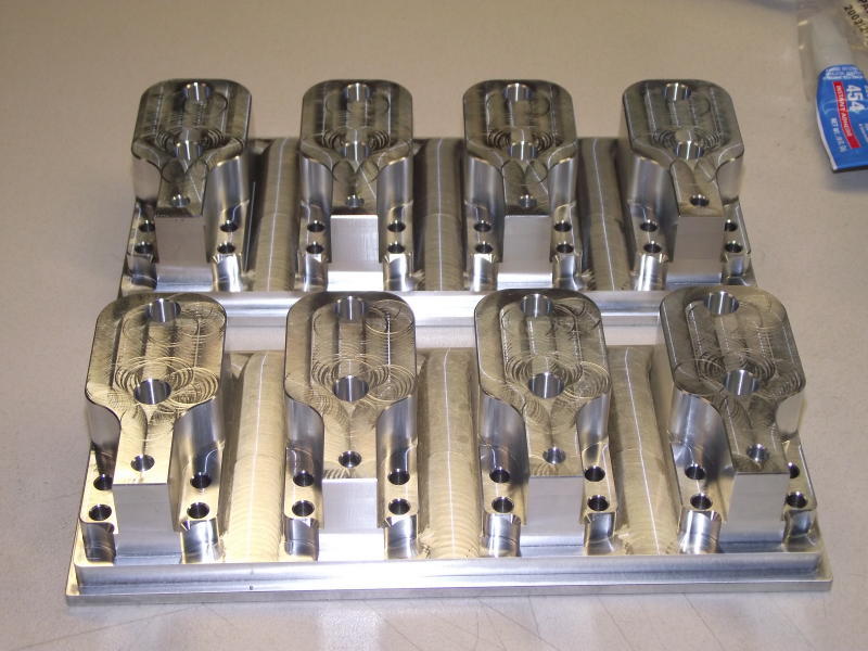
Some machining on the ground
flat aluminum stock used as the fixture base plate.
|
|
|
image020
|
|
|
|
|
FinePix S1800
5/17/2010 10:00:33 PM
|
|
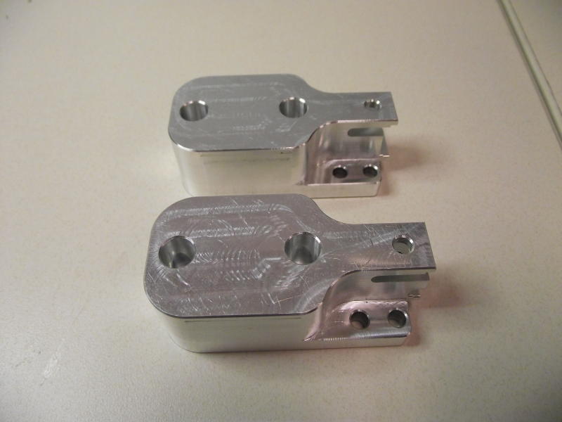
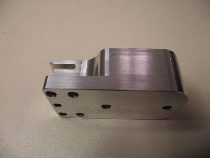
These are the head holders after
the first cnc operation. Notice that all of the edges are chamfered and the
vertical edges all have a small radius machined on them!
|
|
|
|
|
|
image021
|
|
|
|
FinePix
S1800
1/14/2011 11:31:17 AM
|
|
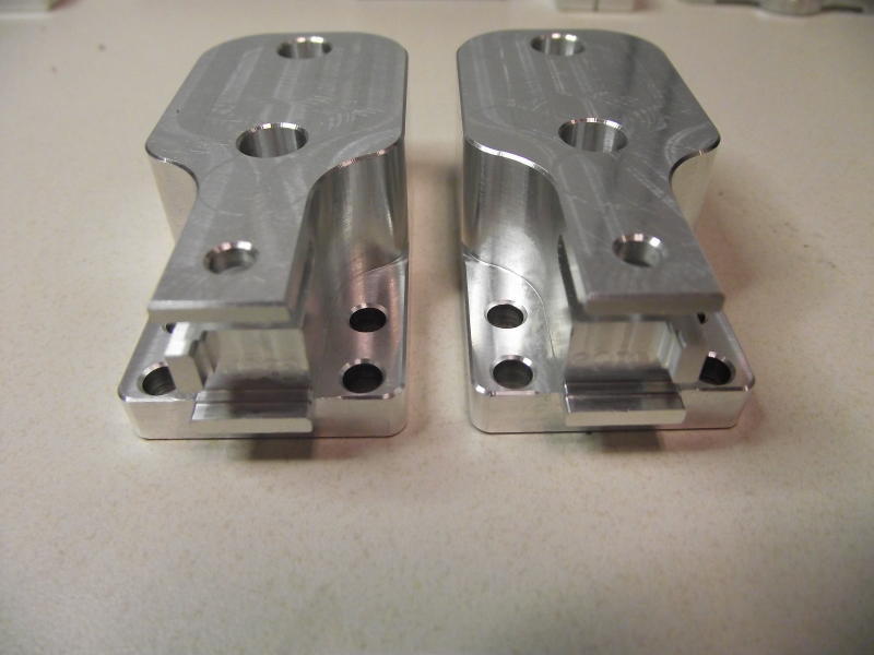
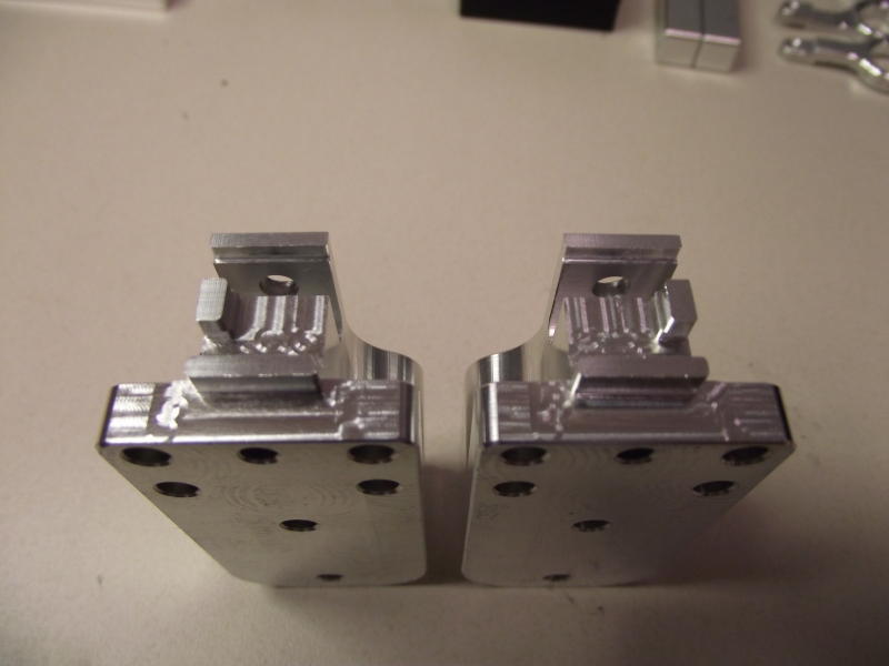
These are the completed
parts after 3 operations!
|
|
|
image022
|
|
|
|
|
FinePix S1800
1/14/2011 11:31:27 AM
|
|
|
|
|
|
|
|
image023
|
|
|
|
FinePix
S1800
1/14/2011 11:31:36 AM
|
|
|
|
|
image024
|
|
|
|
|
FinePix S1800
1/14/2011 11:31:47 AM
|
|
Notice that after the 3rd
and final operation even the bottom side has been machine chamfered!
|
|
|